Welcome to MOV r0, and my first blog post. The goal of this article is to teach you how to JTAG the Raspberry Pi 2 without having to compile a custom kernel to enable the GPIOs to do JTAG. Let’s begin! The tools and equipment I’ll be using today are as follows:
- TIAO USB Multi-protocol JTAG adapter. This device is like a BusPirate on steroids. It’ll do everything. It’s got an FT2232H chip inside, and supports dual-MPSSE. That means we can use UART/JTAG simultaneously, or SPI1/SPI2, or SWD. It’s really an amazing device at a great price. You can find it here (Link)
- Raspberry Pi 2 running Raspbian (Jessie)
- Female-to-female jumper wires (Can’t ever have enough of these)
- Host system is using Ubuntu Mate 15.04, with latest OpenOCD and FTDI support
Grab the latest build of OpenOCD (On your host machine, not your Raspberry Pi, these directions are specific to an FTDI JTAG adapter)
git clone git://git.code.sf.net/p/openocd/code

sudo apt-get install libtool autoconf texinfo libusb-dev libftdi-dev libusb-1.0.0 libusb-1.0.0-dev pkg-config

cd code
./bootstrap
./configure --enable-maintainer-mode --enable-ftdi
make
sudo make install
Next we’re going to compile a small binary written by the guys over at SysProgs (Link). This will be done on the Raspberry Pi 2 itself.
I’ve modified the original source to change the peripheral base address to support the Raspberry Pi 2. (Working on some server stuff.) The peripheral base went from 0x20000000 to 0x3F000000. NOTE: Before we compile this, we must edit the peripheral base and change it to 0x3F000000. I use nano since it’s my favorite editor.wget http://sysprogs.com/VisualKernel/tutorials/raspberry/jtagsetup/JtagEnabler.cpp nano JtagEnabler.cpp (Replace 0x20000000 with 0x3F000000) g++ -o JtagEnabler JtagEnabler.cpp
Remember the location of this binary on your RPi2, we’ll need it later. This binary simply changes the GPIOs to ALT functions (i.e, routes these specific GPIO pins to an alternative function, which in this case is routed to the ARM JTAG pins.) 3. At this point, we’ll need to create a configuration file for OpenOCD to interface with the RPi2. We’ll use the configuration file found from Jitomesky’s GitHub (Link).
wget http://movr0.com/files/rpi2.cfg
Finally, we’re ready to connect to the Pi’s JTAG pins. JTAG RPi2 GPIO VREF* Pin 1 nTRST Pin 15 GND Pin 9 TDI Pin 7 TMS Pin 13 TCK Pin 22 TDO Pin 18 *Note: Pin 1 is optional, but useful for verifying voltage level. �With our Pi wired up and ready to go, we’ll start by activating the JTAG pins using the binary we compiled earlier:
sudo ./JtagEnabler
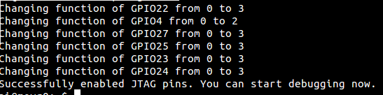 JtagEnabler executing Next we’ll fire up OpenOCD and attempt to connect! (You may need to use a different configuration file for your interface depending on which device you are using. FTDI devices are cheap and work very well) Since I have the TUMPA, I am using the TUMPA configuration file in the FTDI devices folder.
sudo openocd -f interface/ftdi/tumpa.cfg -f rpi2.cfg
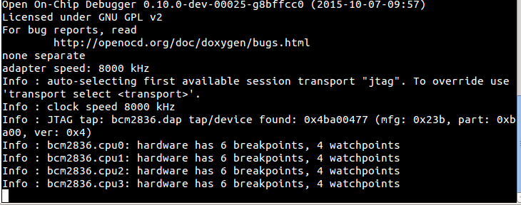 Raspberry Pi 2 connected to OpenOCD
 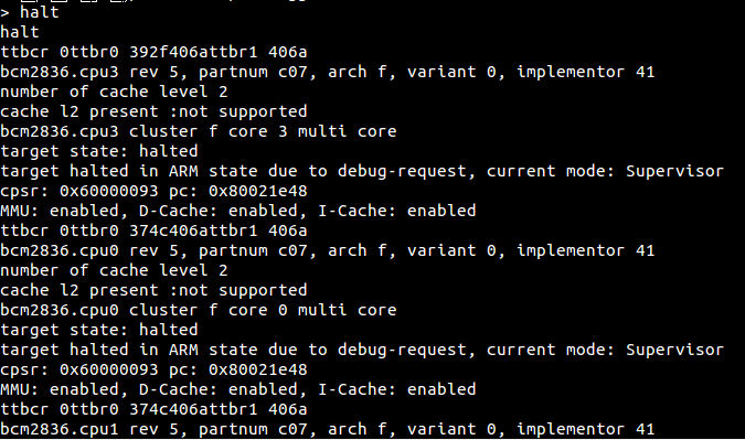 Halting the four cores If all goes well, we should see the four cores halt, and we’re ready to debug. If you have any questions or comments, please post in the comment section below! Thanks for reading. (Note: I’m hoping to put together a SWD tutorial soon, so c’mon back in the near future.)